PIC microcontroller In Circuit Debuggers
Here are some details on a few In Circuit Debugger clones and a programmer for Microchip PIC microcontrollers, which I built about 8 years ago. I dug them out in recent times in order to work on a new PIC project I have in mind.
Now, the way to get the best out of the ICDs is to use Microchip’s MPLAB IDE, which allows building the binary, programming into the target (In circuit, of course), running, setting breakpoints, and the usual debugging functionality, all with a few mouse clicks.
The IDE is free, however as new versions have come out over the years, support for some of the older hardware has been dropped. The older MPLAB versions are still available, specifics on which to use for each tool are given below. For that reason, I would suggest that anyone starting fresh with PIC micros download themselves a copy of the latest MPLAB X release, and purchase a PICkit 3 to program and debug with.
ICD1
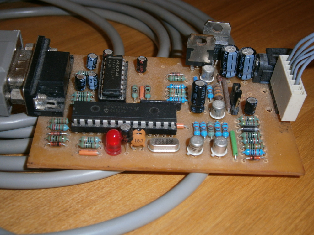
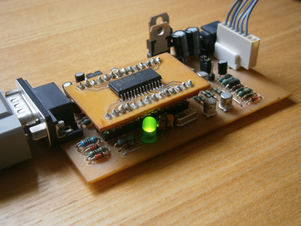
This is a clone of the Microchip MPLAB ICD1, based on a layout by a chap called Patrick Touzet. Details of constructing your own example are here.
|
|
| I can't remember why, but I ended up building two of these. The second unit (Lower) has a surface mount PIC16F876 connected to the DIP socket via an improvised adapter, but the operating frequency is low enough that this works fine. I only had an SOCC packaged version of the chip to hand at the time, ya see. |
Unfortunately, the last version of MPLAB to support the ICD1 is 5.70.40, released sometime in the ’90s. On the plus side, MPLAB 5.70.40 supports debugging PIC16Fxxx targets using the ICD1, integrates well with older Hi-Tech PICC/PICC18 compilers, and steps through code with this version of the ICD1 nice and quickly.
Unfortunately, a lot of the PIC16Fxxx chips supported in MPLAB 5 are no longer in production, so that setup is definitely a no-go for new designs. Also the age of the software does bring other usability issues, such as its ignorance of the existence of any mapped network drives in Windows, making it awkward when used in a VM.
|
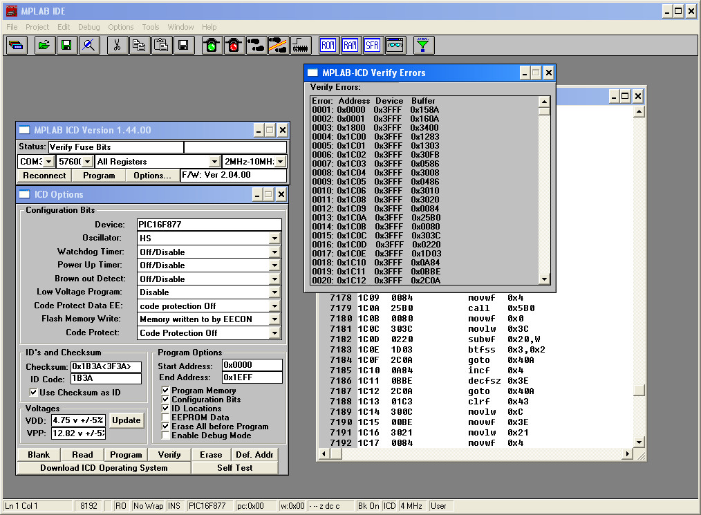
| A brief glance at the MPLAB 5 IDE UI will tell you that it is indeed very old. |
Nevertheless, what follows are some of my notes on its use, further to those in the link above.
ICD board setup
Power supply:
JP1 controls power supply source. JP1 pin 1 is furthest from DC jack.
Bridge the pins:
- 1-2: Power from DC jack
- 2-3: Power from target
ICSP connector:
ICSP pin 1 is furthest from DC jack. Pin 1 is to MCLR on target.
When powered on, ICD LED will flash. When serial port connected, LED is constant on.
Initial firmware load
Program the PIC16F876 on the ICD using a regular PIC programmer and the ICD firmware file (C:\Program Files\MPLAB\MPL876.HEX in a default MPLAB 5.70.40 installation).
To just program a hex file using the ICD1 in MPLAB 5
Switch to ICD development mode. Choose File->Import, select the hex file. Data is visible by choosing Window->”Program Memory”. Then just erase, program, verify, in the ICD window.
ICD2
The Microchip MPLAB ICD2 was an updated version, the proper official model came with the choice of USB as well as RS-232 connection to the development host. My version was based on the schematic provided with the assembly instructions for the “Inchworm+ ICD2” PCB, available in the past through blueroomelectronics.com (Apparently now defunct). The instructions, with schematic, for that board are here. I was getting into Cadsoft Eagle at the time, so I re-entered the schematic and laid it out for single sided construction, grab the Eagle files here.
|
| My single sided ICD2. |
The last version of MPLAB to support the ICD2 is 8.92, only one major version behind the current MPLAB X (No I’m not sure what happened to 9 either). It works well enough from a Windows VM with a USB-serial adapter connected through to the guest OS. MPLAB 8 supports many more of the latest chips, and also integrates well with the free Microchip XC compilers (Released after they bought Hi-Tech). There is a delay when stepping through code, but despite that, this is my daily runner for PIC development at present.
If anyone reading this did decide to build one (Unlikely) here are some notes on it’s use, specific to my ICD2 board layout:
Board setup
Power supply
Three pin jumper J1 is furthest from serial port, controls whether ICD2 can control VCC on target, if target power is supplied through the ICSP connector. Pin 1 is furthest from serial port connector.
Bridge the pins:
- 1-2: Target power always on.
- 2-3: Target power is controllable through MPLAB (Requires fitting of the optional Q1 P-FET).
J2 is nearest serial port, controls VPP voltage. J2 pin 1 is on side nearest serial port.
Bridge the pins:
- 1-2: 12V VPP.
- 2-3: 13V VPP.
ICSP connector
ICSP pin 1 is furthest from DC jack. Pin 1 is to MCLR on target.
Initial firmware load
Program ICD2_Bootloader.hex into the PIC16F877A using a regular PIC programmer, before inserting into socket on the ICD2 board.
In MPLAB 8, after choosing ICD2 in the programmer menu, selecting a device in the configure menu will download the appropriate firmware to the ICD2 for that device range (PIC16Fxxx, PIC18Fxx etc).
Multi socket JDM
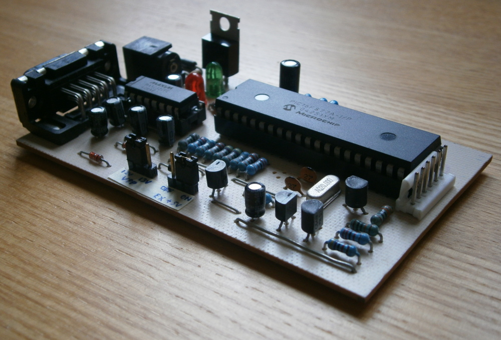
This is a regular PIC programmer, powered and driven over a serial port using the well known JDM circuit. My version was adapted from the Olimex PIC-PG2, with a seperate socket for each DIP package size. No, I’m not sure why I added double width pads for the smaller sockets, ZIF sockets for those DIP sizes wouldn’t need them. It was a long time ago, is all I can say.
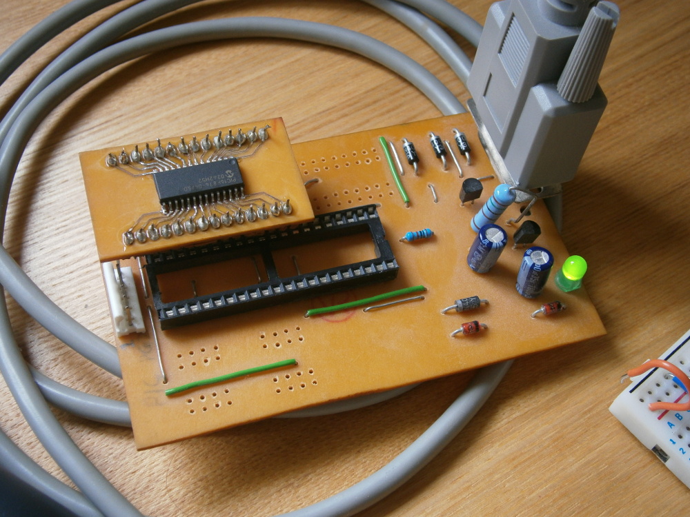
|
| A JDM PIC/EEPROM programmer with separate sockets for each DIP size. Seen here programming the surface mount PIC mounted on an adapter for my second ICD, in the 28 pin DIP socket. |
The Eagle files for my layout of the JDM are here.
If you use this, or buy a PIC-PG2, or any other JDM based programmer, bear in mind you’ll need a real RS-232 port, which means one in a desktop PC usually. An FTDI based USB-RS232 adapter will drive the correct signals, and the LED will flash appropriately, but the 5V swing as opposed to the +/-12V on a real serial port means the VPP will be nowhere near the 12V required, so no actual programming will occur. Find an old desktop PC if necessary.
Programming software
For a JDM, use one of these, here are my experiences:
IC-Prog: Multiple tabs, which is good for comparing data when reading back from a device etc, unfortunately wouldn’t program the full memory range of my PIC16F876 correctly.
PICPgm: Did program my PIC16F876 correctly, does the job.
WinPicProg: Haven’t tried this one.
Happy PIC development!